Remote operation of ballast, cargo and service valves from the cargo control room. Hydraulic, electro‑hydraulic, electric and pneumatic actuators, applied mainly to butterfly valves.
System composition
- Control console in the cargo control room
- Hydraulic power unit
- Solenoid valve cabinets, and solenoid valve deck boxes where the valves are in a hazardous area
- One actuator on each valve
- Emergency hand pumps and hand pump connection blocks
Each system is engineered to the shipyard’s specification, the owner’s requirements and the rules of the classification society.
Actuators
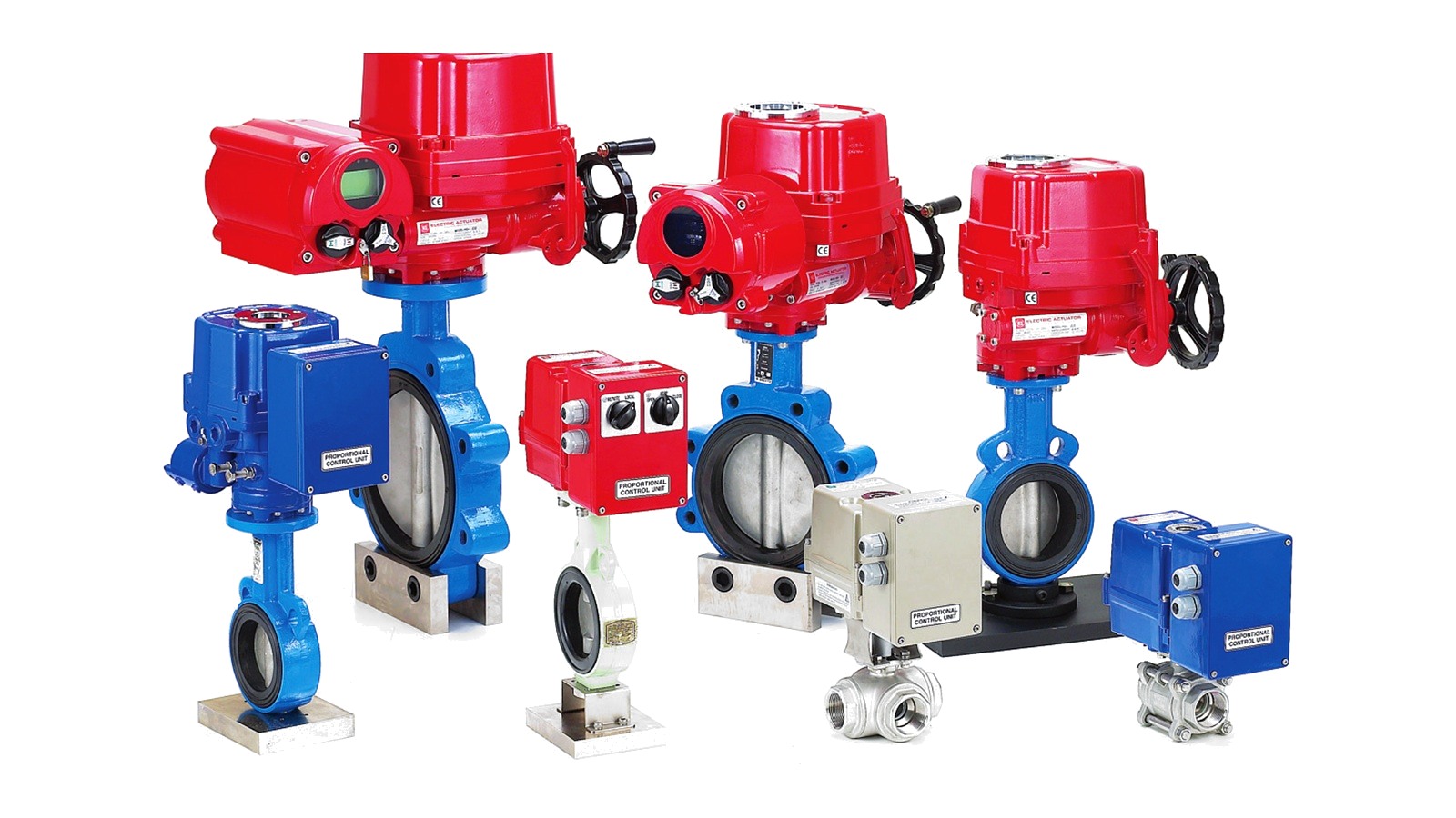
Four types are offered. All are quarter‑turn and are used mainly on butterfly valves. The four are set out against the same headings below.
Hydraulic actuator — HLT series
| Valves | Butterfly valves principally; also plug and ball valves |
|---|---|
| Design | Rack and pinion, quarter-turn |
| Driven by | Hydraulic oil, 16 MPa (160 bar) maximum working pressure |
| Output torque | 215 to 12,821 N·m across seven sizes, constant through the quarter-turn |
| Travel | 90° ±5 |
| Mounting flange | ISO 5211, F05/F07 to F25/F30 |
| Manual operation | Stationary hand pump, portable hand pump or manual hydraulic transmitter, through quick connectors or fitted pipe |
| Notes | Rated for submerged service, dry spaces, open deck and hazardous areas. Local visual indicator; limit switch box available. Tested to BS EN 15714-4:2009 |
Range, all sizes at 160 bar (16 MPa) and 90° ±5:
| Model | Max. output torque | Cylinder volume | Mounting flange | Weight |
|---|---|---|---|---|
| HLT-13 | 215.4 N·m (22 kgf·m) | 28.5 cc | F05, F07 | 15 kg |
| HLT-35 | 586.1 N·m (59.8 kgf·m) | 62 cc | F07, F10 | 20 kg |
| HLT-70 | 1,097.2 N·m (112 kgf·m) | 115 cc | F10, F12 | 31 kg |
| HLT-135 | 2,110 N·m (215.2 kgf·m) | 223 cc | F12, F14 | 41 kg |
| HLT-300 | 4,747.5 N·m (484.4 kgf·m) | 499 cc | F14, F16 | 81 kg |
| HLT-500 | 8,510.4 N·m (868.3 kgf·m) | 895 cc | F16, F25 | 140 kg |
| HLT-800 | 12,821.3 N·m (1,308.2 kgf·m) | 1,350 cc | F25, F30 | 204 kg |
Electro-hydraulic actuator — EHLT series
| Valves | As the hydraulic actuator on which it is built |
|---|---|
| Design | Hydraulic actuator with an integral micro power unit |
| Driven by | Its own electric motor and pump; no hydraulic ring main required. Normal or Ex-proof motor |
| Output torque | As the hydraulic actuator on which it is built |
| Travel | 90° ±5 |
| Mounting flange | ISO 5211 |
| Manual operation | As the hydraulic actuator |
| Notes | Aluminium body and main block. The main block carries the relief valve and pilot check valve; the pump is mounted inside the oil tank. Limit switch box for position feedback. IP68 available on the double acting type |
Electric actuator — EQ series
| Valves | Butterfly, ball and plug valves, and dampers |
|---|---|
| Design | Electric, quarter-turn |
| Driven by | Electric motor |
| Output torque | Sized to the valve torque |
| Travel | Quarter-turn |
| Mounting flange | ISO 5211 |
| Manual operation | Hand wheel |
| Notes | Four limit switches as standard, two for operation and two spare. Space heater, captive cover bolts and an 11-pin terminal block. Rechargeable battery backup actuator available for emergency operation |
Pneumatic actuator — HP series
| Valves | Butterfly, ball, plug and damper valves |
|---|---|
| Design | Rack and pinion, or scotch yoke, quarter-turn |
| Driven by | Instrument air, 10 bar maximum working pressure. Double acting, or single acting with spring return |
| Output torque | Sized to the valve torque |
| Travel | Quarter-turn |
| Mounting flange | ISO 5211, DIN 3337, VDI/VDE 3845 and NAMUR |
| Manual operation | Manual override available to order |
| Notes | −20 to +80 °C as standard; −35 to +150 °C available |
Hydraulic power unit
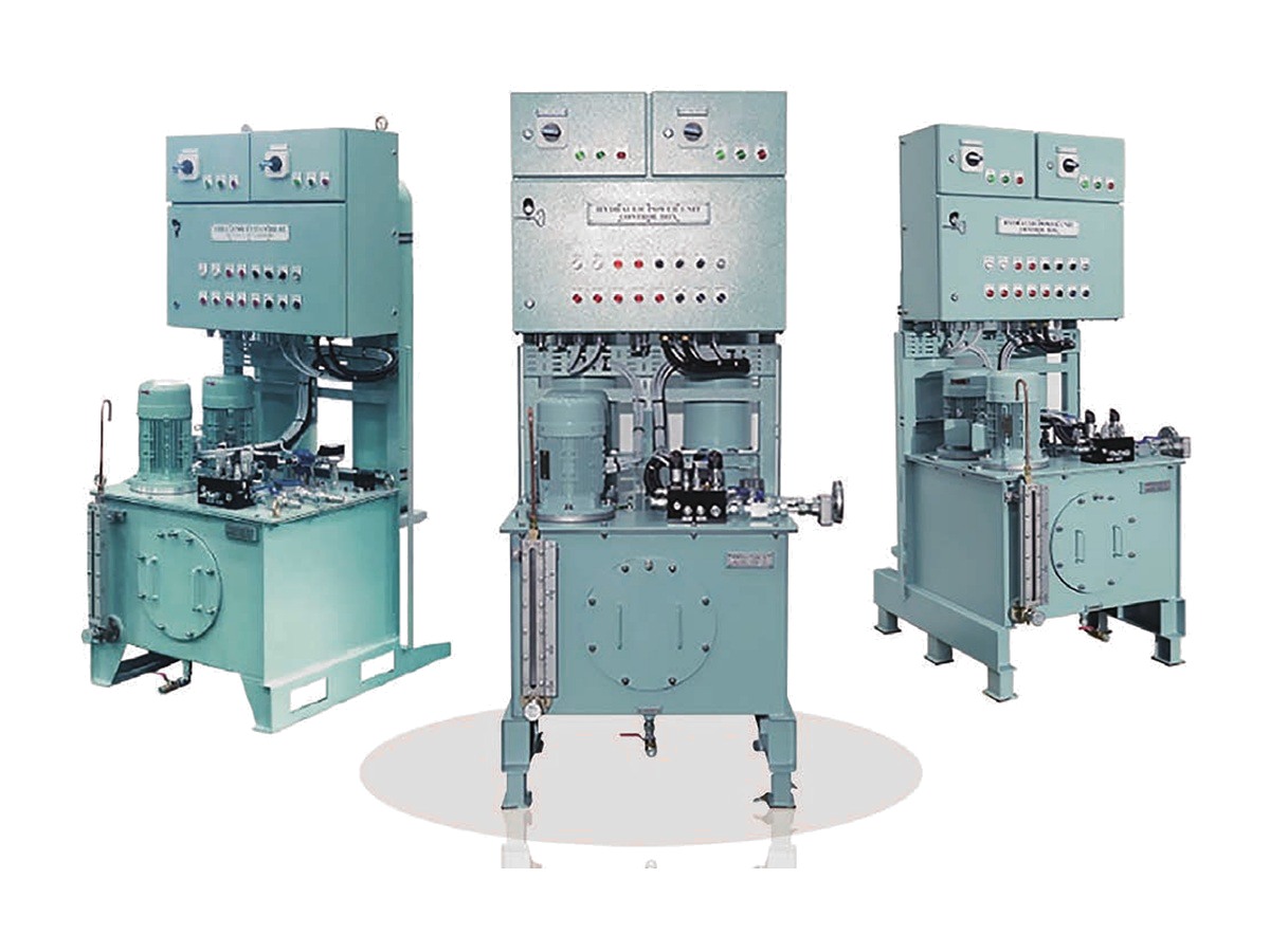
Two pumps, one running and one on standby, with automatic changeover if the working pressure falls away. The control box carries pump control and selection, and alarms for pressure, level and temperature. The unit delivers above the system working pressure and a pressure reducing valve brings it down to the figure the system is set to work at.
The accumulator makes up internal leakage so the pumps do not cycle, holds the pressure steady, and retains enough capacity to operate the valves nominated by the owner under emergency conditions.
| Components | Hydraulic pump, electric motor, accumulator, pressure relief valve, pressure reducing valve, pressure switch for control and pressure switch for alarm each with gauge and transmitter, level indicator, level switch, filter and indicator, temperature switch |
|---|---|
| LNG carriers | Two main pumps and a topping-up pump that holds system pressure when no valve is operating. Piston type and self-regulating pumps are used to keep the pressure constant |
Solenoid valve cabinet and deck box
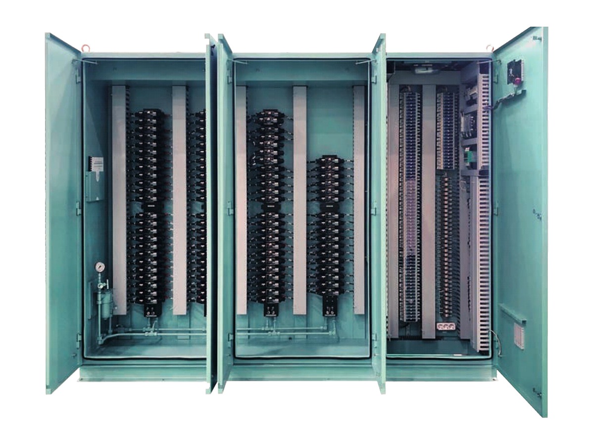
The cabinet is divided into a hydraulic part and an electric part. It works each valve according to its function, passes the valve position signal to the console or computer, and receives the position signal back.
| Hydraulic part | Solenoid valves, flow control valves, manifold blocks, pressure filter and feedback components |
|---|---|
| Electric part | Wiring for valve control and for the feedback signal |
| Deck box | For hazardous areas — passage ways and pump or machinery rooms on tankers and gas carriers. IP56 steel cabinet, intrinsically safe solenoid valves (Ex ia), manifold block, pressure filter unit, stop valve, flow control valve, ESD block and accumulators |
| Emergency shutdown | De-energising the ESD solenoid opens the oil way to the closing chamber of the actuator and the valve shuts. Accumulator capacity is normally sized for two strokes of the ESD valves |
Control console and local control cabinet
The console operates and monitors the system, with valve control switches and position indication on a mimic plate. It also carries the tank level gauging and cargo monitoring displays, and is arranged to the shipyard’s requirement.
| Console | Steel structure, mimic board with valve control switches and indication, hydraulic power unit remote control panel, electric power distribution, pressure and tank level gauges, telephone, clock and monitor |
|---|---|
| Local control cabinet | Free-standing steel cabinet with touch panel, for local operation and monitoring of the system |
Accessories
- Stationary hand pump — hand pump unit with stainless steel tank, pressure gauge, hand lever and valve part. Protection box, dual or multi valve control, indication and single acting operation available.
- Portable hand pump — hand pump unit with stainless steel tank on a wheeled frame, two 5 m flexible hoses with self-sealing couplings and a 0 to 250 bar gauge. Used when the power unit is out of service or an actuator or valve is being worked on.
- Hand pump connection block — block, connectors, stop valve and a seat with protective cover, for valves inside cargo and ballast tanks or otherwise out of reach. Fitted in an accessible dry space or on deck.
- Limit switch box — mounted on the actuator. Dry contact 2 × SPDT, potentiometer 0 to 1 kΩ, or 4 to 20 mA output. Ductile cast iron FCD450 for sea-water service; flag indicator available.
- Flow meter — reads the oil flow while an actuator is running, to confirm the valve has opened or shut. Electric output 4 to 20 mA or dry contact; mechanical output 0 to 1 kΩ or dry contact.
- Safety block with isolating valve block — a double pilot check valve holds the actuator’s last position if hydraulic pressure is lost, two relief valves drain the cylinder above the set pressure, two isolating valves cut the supply to the actuator, and a by-pass valve allows the line to be flushed. 160 bar maximum working, 180 bar relief cracking, G1/4 connection, 30 L/min at 120 bar, −25 to +100 °C, 3 kg.
- ESD block — three pilot check valves and two relief valves. On emergency shutdown the actuator is driven from an auxiliary source such as the accumulators. 160 bar maximum working, 180 bar relief cracking, G1/2 emergency connection, −25 to +100 °C, 7 kg.
Integration and approval
Valve control can run within Hanla’s integrated alarm, monitoring and control system, which puts the valves on the same workstations as the engine room auxiliaries. Workstations sit in the cargo control console and the I/O modules in the local cabinets, connected over Ethernet TCP/IP and CAN. Type approved by ABS, BV, CCS, DNV, KR, LR and NK.
Send the valve list with sizes, types and required torques, together with the control room arrangement, and we will quote.
From the range