
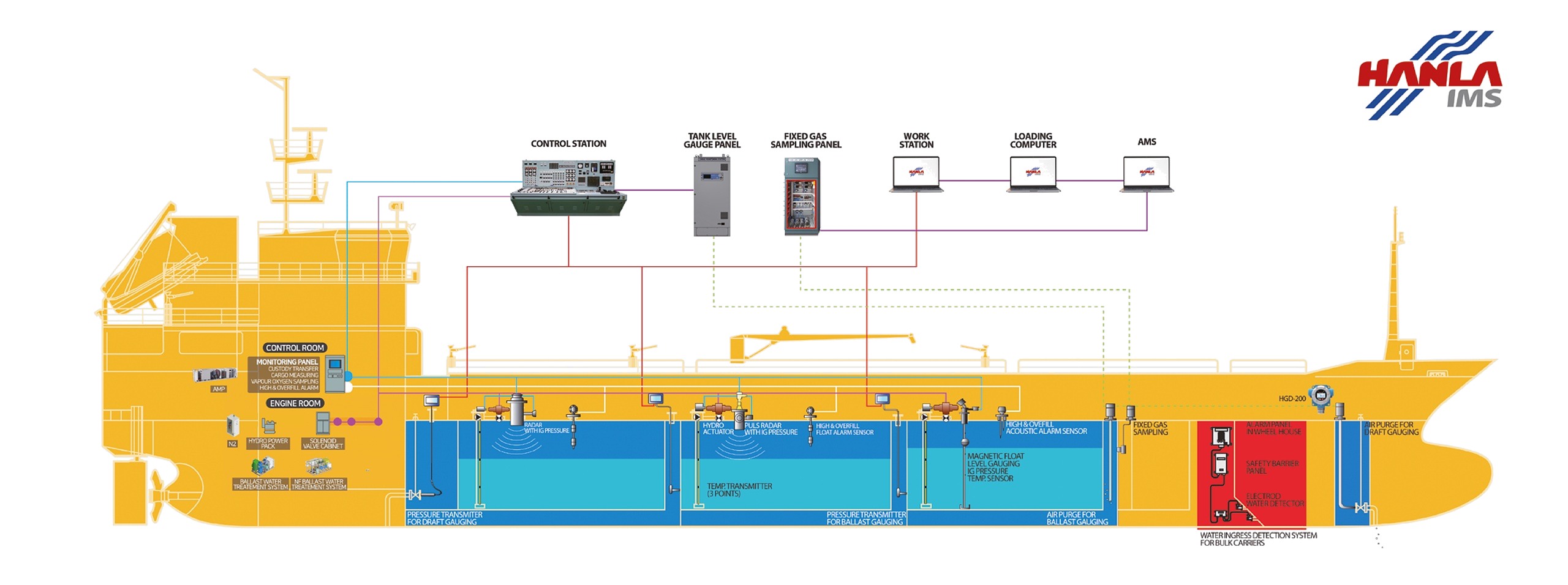
Level, temperature, pressure and gas monitoring for cargo and ballast tanks — from the sensors on deck to the display in the cargo control room. Supplied for oil and chemical tankers, gas carriers, bulk carriers, FPSOs and drill ships.
What the system covers
- Cargo tank level, temperature and pressure — pulse radar›
- Cargo tank level, temperature and pressure — FMCW radar›
- Cargo tank level, temperature and pressure — magnetic float›
- Independent high level and overfill alarm›
- Vapour emission control›
- Fixed gas sampling — pump room, ballast and void spaces›
- Pump and manifold pressure monitoring›
- Tank remote sounding — ballast, fuel oil and draft›
- Water ingress detection — bulk carriers›
- Loading computer›
Sensor signals gather at an I/O panel and pass to the cargo monitoring display, the workstations and the loading computer over RS-485 Modbus RTU. Individual gauges, switches and transmitters are on the level gauges, level switches and level transmitters pages.
Cargo tank monitoring — pulse radar

PS60 series, supplied with Vega. Short microwave pulses are emitted by the antenna, reflected from the product surface and received back; the time from emission to reception gives the level. Two emitting frequencies are offered — compact high-frequency sensors where accuracy matters most, and low-frequency C band sensors that penetrate foam and heavy condensation. Readings are unaffected by steam, gas composition, pressure and temperature change.
| Model | Application | Range | Process temp. | Process press. | Accuracy |
|---|---|---|---|---|---|
| PULS 61 | Aggressive liquids in small vessels, easy process conditions | to 35 m | −40 to 80 °C | −1 to 3 bar | ±2 mm |
| PULS 62 | Storage and process vessels, arduous conditions | to 35 m | −200 to 450 °C | −1 to 160 bar | ±2 mm |
| PULS 63 | Aggressive liquids, arduous conditions | to 35 m | −200 to 200 °C | −1 to 16 bar | ±2 mm |
| PULS 65 | Aggressive liquids, easy process conditions | to 35 m | −40 to 150 °C | −1 to 16 bar | ±8 mm |
| PULS 66 | Storage and process vessels, arduous conditions | to 35 m | −60 to 400 °C | −1 to 160 bar | ±8 mm |
| PULS 68 | Large solid vessels | to 75 m | −200 to 450 °C | −1 to 160 bar | ±2 mm |
| Deck arrangement | Radar, temperature and pressure sensor on one deck mounting, with a local level indicator and a local temperature and pressure indicator |
|---|---|
| I.G pressure transmitter | TLP-100S, 800 to 2000 mbar, accuracy ±0.2%, Ex ia IIB T4 |
| Temperature transmitter | TLP-100S, PT1000 RTD, accuracy ±0.3 °C, −20 to 80 °C, up to three points per tank, Ex ia IIB T4 |
| Communication and safety unit | 24 VDC. Up to 24 radars on cargo tanks and 31 on ballast and other tanks. One RS232/485/422 input and three outputs, four relay outputs NO/NC, Modbus RTU, 0 to 60 °C |
Cargo tank monitoring — FMCW radar
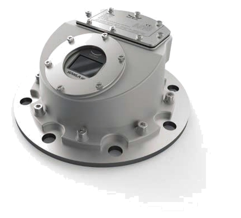
HRD-28 series, developed by Hanla for tanker service and covering level, temperature and pressure in the cargo tank. The level transmitter works on frequency modulated continuous wave radar; measurable products include gasoline, diesel, heavy oil and kerosene. Sensors in the hazardous area are intrinsically safe.
| System | HRD-28R level transmitter, HRD-28P pressure transmitter, HRD-28T temperature transmitter, HRD-28B safety module for supply and communication into the hazardous area, HRD-28C communication unit to the monitoring or loading computer |
|---|---|
| Range | Up to 35 m |
| Display resolution | 0.1 mm |
| Sensor accuracy | Up to ±3 mm |
| Antenna beam angle | 12° (HPBW) |
| Local indicator | 2.5 inch graphic LCD showing level, temperature and pressure |
| Pressure transmitter | HRD-28P, 800 to 2000 mbar, accuracy 0.3% of full scale, output 0.5 to 4.5 VDC, IP67, Ex ia IIB T6 |
| Temperature transmitter | HRD-28T, two-wire PT1000 at 0 °C to IEC 751 class B, −50 to +150 °C, IP67, Ex ia IIB T6 |
| Operating temperature | −35 to +70 °C; storage −40 to +85 °C |
| Communication | RS-485 Modbus RTU |
Cargo tank monitoring — magnetic float
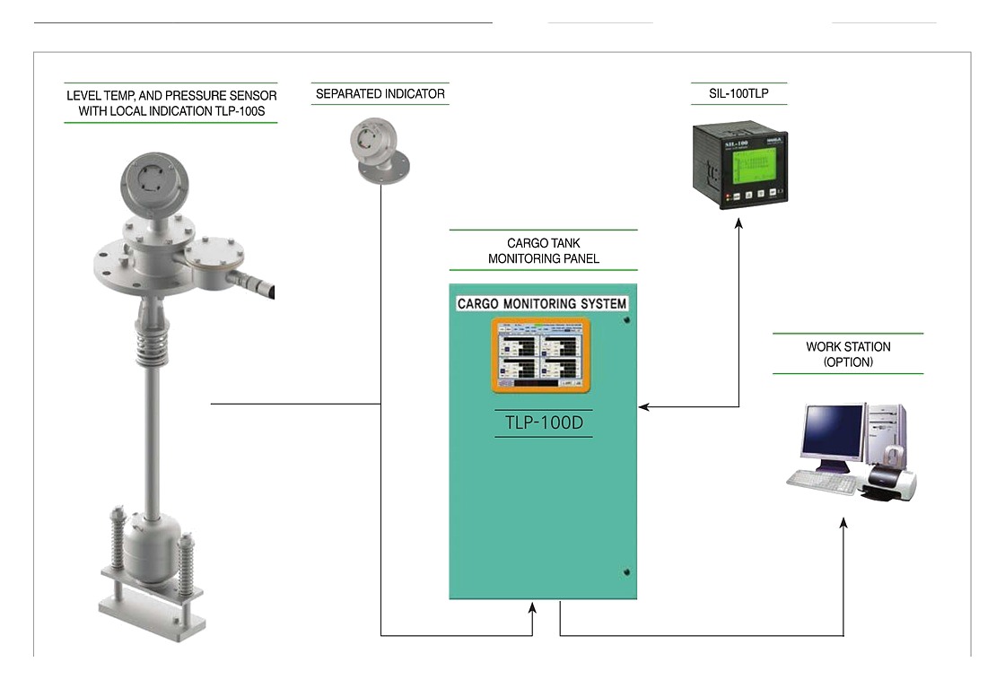
TLP-100 series. Float position is read by Hall IC elements rather than reed switches, which removes contact fusing and the drift that goes with it. Measurement does not depend on the conductivity or dielectric constant of the cargo, so the same gauge suits crude oil carriers, product carriers, chemical carriers and coaster tankers.
| Local gauge | TLP-100S — level by magnetic float and Hall IC element, temperature by PT-100 RTD, pressure by ceramic sensor |
|---|---|
| Measuring range | Level to 20 m; temperature −25 to +125 °C; pressure 900 to 1300 mbar |
| Accuracy | Level every 10 mm as standard, 5 mm to order; temperature ±1.0 °C |
| Local indication | Six-digit LCD on a selector: level in 5 mm units 0 to 20.000 m, and upper, middle and lower temperature in °C or °F |
| Remote indicator | SIL-100TLP — individual tank LCD, four level alarms (HH, H, L, LL) on 24 tanks, two temperature alarms on each of three elements, four pressure alarms, RS-485 Modbus |
| Multi-tank monitor | TLP-100D — 10.4 inch touch screen with mimic display, per-tank detail, volume and average temperature calculation and trend curves. Two RS232 plus selectable RS232/422/485 |
| Multiplexer | TLP-100MUX — eight 4 to 20 mA inputs, 24 tank sensors for level, temperature and pressure, 13 relay contact outputs |
| Data transmission | Two-core cable carries level, maximum and three-point temperature data to the control room by serial BCD signal, and the supply to the deck on the same pair |
Independent high level and overfill alarm

A second, independent alarm on the cargo tank, designed to USCG requirements and called for by the IBC Code. The reed switch in the sensor is actuated by a magnetic float; the signal passes through a safety barrier to the annunciator, giving audible and visual alarm on the main panel and an external alarm on the bridge top. High alarm is normally set at 95% of volume and overfill at 98%.
| Models | TMR-701T high alarm; TMR-702T high and overfill alarm |
|---|---|
| Connection | JIS 5K 100A standard; conduit JIS 5K 32A standard |
| Materials | Housing SUS304; flange SUS304 or SUS316; guide pipe and magnetic float SUS316 |
| Contact | SPST, 250 VAC, 0.5 A |
| Accuracy | ±5 mm on level rise or fall |
| Specific gravity | 0.65 to 1.5 |
| Working temperature | −25 to +100 °C |
| Protection | IP56 and above; Ex ia IIC T6 |
| Function test | Lifting-type manual test device on the sensor |
| Alarm panel | AC110/220 V main with DC24 V backup, I.S. barrier, annunciator, power lamp, DC power fail alarm and buzzer; external horn and light |
| Alarm module | AU-160D — 16 contacts, alarm input and escape delay 0 to 99 s, NC or NO channel outputs, common relay, internal buzzer with stop and flicker stop buttons |
|---|---|
| Supply | 24 VDC (18 to 32 VDC), or 110 or 220 VAC. Maximum 4.5 W at 24 VDC |
| Indication | 16 red/green LEDs, one yellow and one green, with first alarm flashing |
| Communication | RS-485; channels set by internal rotary switch or by the Windows setting program |
| Enclosure | Standard DIN 144 × 144 × 86 mm; operating −10 to +55 °C |
| Repeater | AU-160R over RS-485 |
Vapour emission control

Analyses the waste vapour for oxygen content and monitors the pressure on the vapour line. Two cabinets: a detector cabinet in steel on deck near the vapour manifolds, and a monitoring and alarm panel in the cargo control room. Sample tubes run from the sample points to the oxygen sampling selector valve and the mode selector valve, through a filter to the oxygen sensor, and out through the exhaust line on the cabinet.
| Detector cabinet | Flow indicator, flow alarm sensor, 90 micron filter, oxygen sensor, sampling selector valve, mode selector valve, cleaning air stop valve and vapour pressure transmitter |
|---|---|
| Supply | Main AC110/220 V 50–60 Hz; system DC24 V; air supply 4 to 7 bar |
| Inert gas pressure | Display 0 to 200 mbar, high pressure alarm at 120 mbar, low pressure alarm at 10 mbar |
| Oxygen | Display 0 to 25% v/v, high oxygen content alarm at 8% v/v |
| Flow failure | Alarm when the sample flow stops |
| Pressure transmitter | 0 to 200 mbar, 4 to 20 mA, accuracy ±0.2% of full scale, 17 to 28 VDC, Ex ia IIC T4 |
| Oxygen sensor | 0 to 25% oxygen, 4 to 20 mA, accuracy ±2% of full scale, DC24 V, Ex ia IIC T4 |
| Display and alarm unit | OVMS-50, 48 × 96 × 112 mm, 4 to 20 mA input, high and low alarm contacts; 10-channel annunciator with accept horn, accept flash and test |
| Enclosure | Ex ia IIC T4. All stainless steel pressure sensor. Alarm points for oxygen and pressure individually adjustable |
Fixed gas sampling
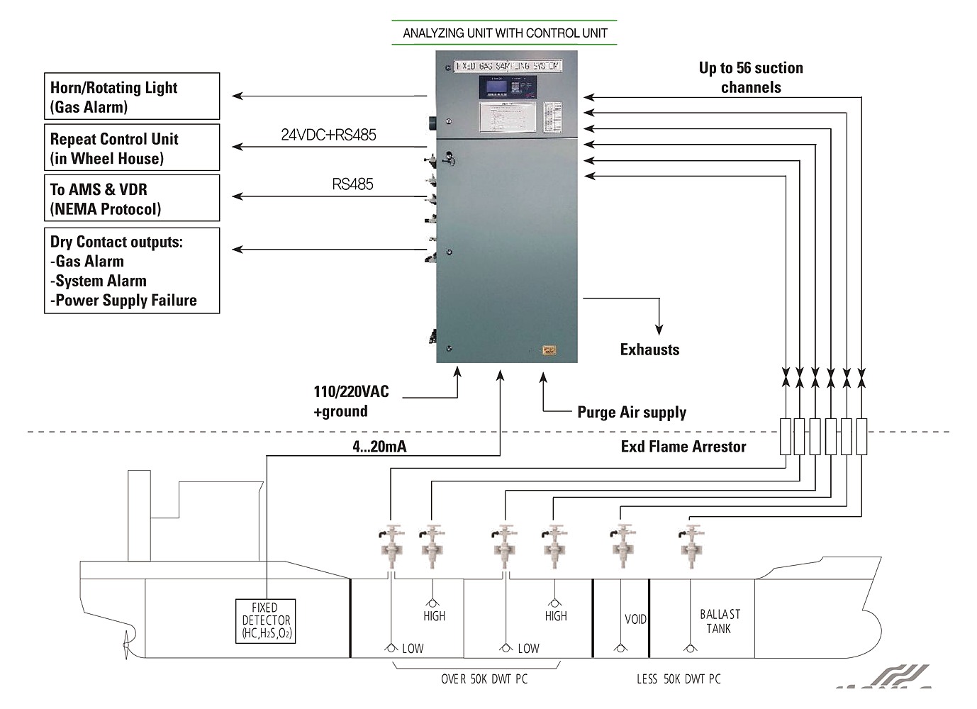
Gas control in cargo tanks, void spaces, the pump room and houses adjacent to cargo storage and handling. Areas are covered by suction sampling onto one or more common sensors as well as by individual local sensors, and alarms are raised when a concentration passes a programmed limit. Complies with ISGOTT chapters 7.8 and 8.2.
| Analysing unit | Cabinet holding the suction sampling components — pumps, solenoid valves, water trap filter, pressure sensor — for up to 48 channels in a modular arrangement, plus an electronic module that monitors up to seven gas sensors in suction or local service |
|---|---|
| Control unit | Panel with LCD screen, status lamps, buzzer and dry contacts, and a keyboard for operation and configuration. Powered at 24 VDC from the analysing unit and linked to it by RS-485; can sit inside the analysing unit or in a remote box |
| Suction channels | Up to 56, on O.D. 8 mm copper pipe. Sampling, circulation and drain water trap outputs on O.D. 10 mm copper pipe to a safe area |
| Analog inputs | Up to 16 4 to 20 mA calibrated inputs for sampling or local sensors |
| Alarm levels | Two adjustable per channel — pre-alarm and main alarm |
| Dry contacts | Gas alarm, system alarm, remote horn or rotating lamp, power supply failure; the control unit adds an internal buzzer and one dry contact |
| Communication | Six RS-485 and one RS232 on the analysing unit; one RS232 or RS-485 on the control unit. Modbus RTU |
| Services | Sensor supply 24 VDC. Instrument air for purge at 7 or 10 bar on O.D. 10 mm copper pipe. Operating 0 to +70 °C. Supply 110/220 VAC |
| Location | Analysing and control units in a safe enclosed space — control room, accommodation or bridge |
| Options | Suction sampling accessories with safety chamber, non-return valves, flame arrestors and shut-off valves, each channel with a flow regulating valve; float-type water check unit in stainless steel, JIS 5K 20A to 40A |
Pump and manifold pressure monitoring
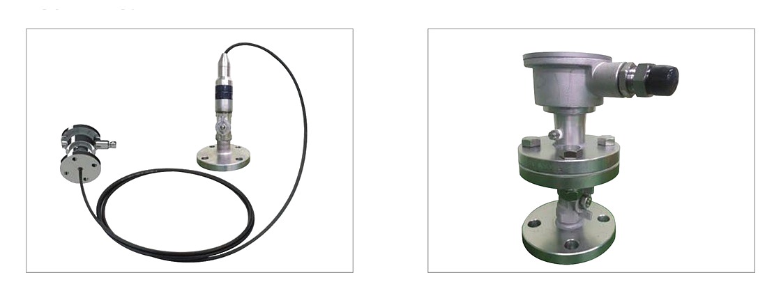
Cargo tank ullage space pressure monitoring with high and low alarm is required by SOLAS 74 chapter II-2 regulation 59, to prevent the tank structure being over- or under-pressurised if the venting system fails. The same equipment covers manifold pressure, pump suction and discharge, and the vapour return line, all indicated in the cargo control room.
| Mounting | On-deck type and submersible type, chosen by where the pressure is taken |
|---|---|
| Accuracy | ±0.2% of full scale at 20 °C |
| Protection | Transducer IP68 at 10 to 40 bar; indoor amplifier box IP66; outdoor amplifier box IP67 |
| Operating temperature | P.E. cable −40 to +80 °C; FEP cable −40 to +120 °C |
| Materials | Ceramic aluminium oxide diaphragm, SUS316L sensor body, PC indoor amplifier box, SCS14 outdoor amplifier box |
| Safety | Intrinsically safe Ex ia IIC T5, with an I.S. barrier in the safe area |
| Indication | Alarm module, wide angle analogue gauge or digital indicator, or 4 to 20 mA to the monitoring panel |
| Applications | Cargo pump, cargo manifold, vapour return line, tank cleaning pump, fire main line and ballast pump pressure |
Tank remote sounding
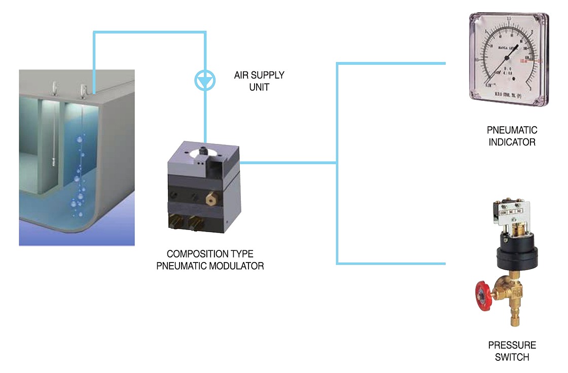
Air purge gauging for ballast, fuel oil, fresh water and draft. A constant low flow of air or neutral gas is fed into a probe open at the bottom of the tank; the back pressure is the hydrostatic head, and the flow regulator holds it steady whatever the supply pressure does. A gauge saver protects the indicator against over pressure, and a blowing valve sends full air pressure down the signal line to clear it.
| Model | Type | Output | Range | Accuracy | Notes |
|---|---|---|---|---|---|
| CT-180-OPN | Pure pneumatic | Pneumatic indicator, 144 × 144 mm | 1 to 40 m | ±1.0% F.S.; ±0.5% to order | No electricity, so no explosion-proof measures needed |
| CT-180-EPN | Electro pneumatic | Pneumatic indicator with electrical output | 1 to 40 m | ±1.0% F.S.; ±0.5% to order | Adds remote electrical reading to the pneumatic loop |
| PL-40P | Electro pneumatic transmitter | 2-wire 4 to 20 mA | 40 to 4000 mbar | 0.2% of scale | Tank-top mounted, automatic bubbling line clearing, Ex ia IIC T6 |
| Air supply | Flow rating 10 to 80 Nl/h; supply setting pressure 4.5 kg/cm² on CT-180; 4 to 10 bar on PL-40P |
|---|---|
| Signal line | O.D. 8 or O.D. 10, up to 400 m between the head and the indicator |
| Working temperature | −30 to +70 °C on CT-180; −20 to +70 °C on PL-40P |
| Air purge head | Dual check type safety chamber, naval brass with SUS304 chamber and SUS316 float, JIS 5K 25A or 5K 20A, working pressure to 10 kg/cm². Keeps liquid out of the line if the air supply fails, and carries a local test device |
| Indicator | 144 × 144 mm, class 1.5 standard with class 1.0 and 0.5 to order, graduated in height or volume, with a zero adjuster |
| Display | PL-40P feeds analogue bargraph and numeric level, volume from the tank table, temperature and alarm status to a PC, over analogue or RS-485 |
Water ingress detection

For bulk carriers under SOLAS regulation XII/12 — cargo holds, closed dry and void spaces where the volume exceeds 0.1% of the ship’s displacement at summer load waterline, and ballast tanks forward of the collision bulkhead. Conductive electrode level switches detect water at the pre-alarm and main alarm levels; the signal passes through an intrinsically safe barrier to the main alarm panel on the navigation bridge.
| Detection | Conductive electrode type level switch; the low-value AC circuit across the electrodes is read by a signal conditioning instrument, which offers a relay contact to the alarm panel |
|---|---|
| Accuracy | ±3 mm |
| Operating voltage | 20 to 250 VAC, 50/60 Hz; response resistor 1 to 200 kΩ |
| Relay output | 2 A AC or 1 A DC |
| Protection | IP66/68; working pressure 0 to 5 kg/cm²; −20 to +80 °C |
| Signal conditioning | I.S. type barrier, EEx ia IIC |
| Main alarm panel | AC110/220 V 60 Hz with DC24 V standby, on the navigation bridge. No limit on the number of detection points. Visual and audible pre-alarm and main alarm per point, repeat panel output, common buzzer, AC/DC power fail alarm and reset, lamp test, malfunction alarm, time delay 0 to 99 s, dimming and flicker stop. Wall or console mounting |
| Overriding device | Provided on the panel for holds used to carry water ballast, to SOLAS XII/12.1, with continuous visual indication while a detector is deactivated and automatic reactivation below the lowest level alarm point |
| Model code | HWID with P16 for 1 to 16 detection points, P32 for 17 to 32 and POV over 32; sensor enclosure E for Ex-type e or W for weather proof |
Loading computer
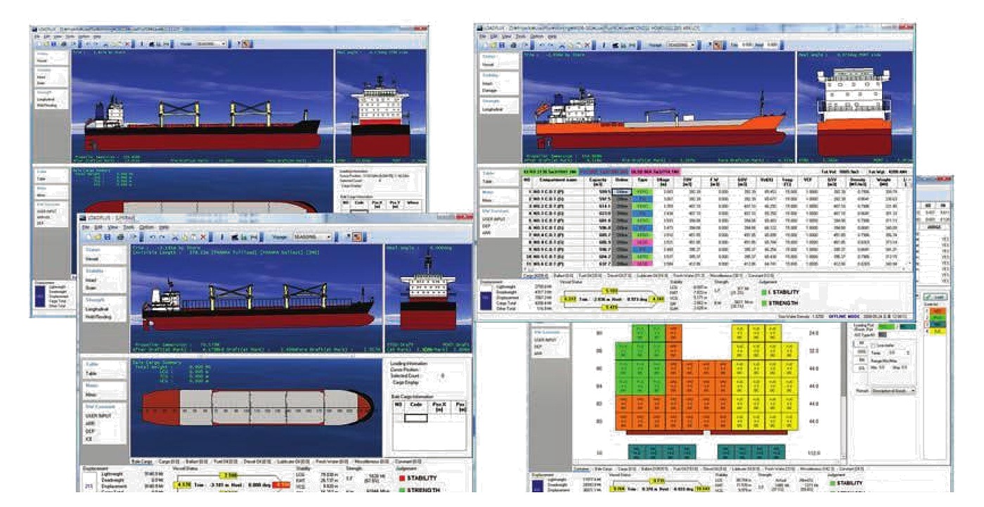
LOADPLUS calculates and controls loading, stability and strength, and simulates cargo distribution. Loads are defined and edited by clicking the tank plan or by table, and the results come back as class approved documents with the items calculated by rule.
- Loading and unloading sequence
- Hydrostatic calculator with graph
- Draft survey calculation
- User-defined damage case
- Visibility and air draft calculation
- Cargo code definition
- Variable report printout, and an online interface to the other equipment on board
Send the tank plan with the tank list, the cargoes carried and the class the ship is built to, and we will put a system together and quote.