
EcoGuardian™ NF — ballast water treatment by side-stream electrolysis, with no filter in the ballast main. 130 to 6,000 m³/h, to the IMO D2 standard and 33 CFR 151.2030, with USCG type approval.
On this page
- Ballasting — how the water is treated›
- De-ballasting — neutralisation›
- The units›
- General specification›
- Range and dimensions›
- Retrofit›
- The 3B ballast package›
- Approvals›
Ballasting — how the water is treated
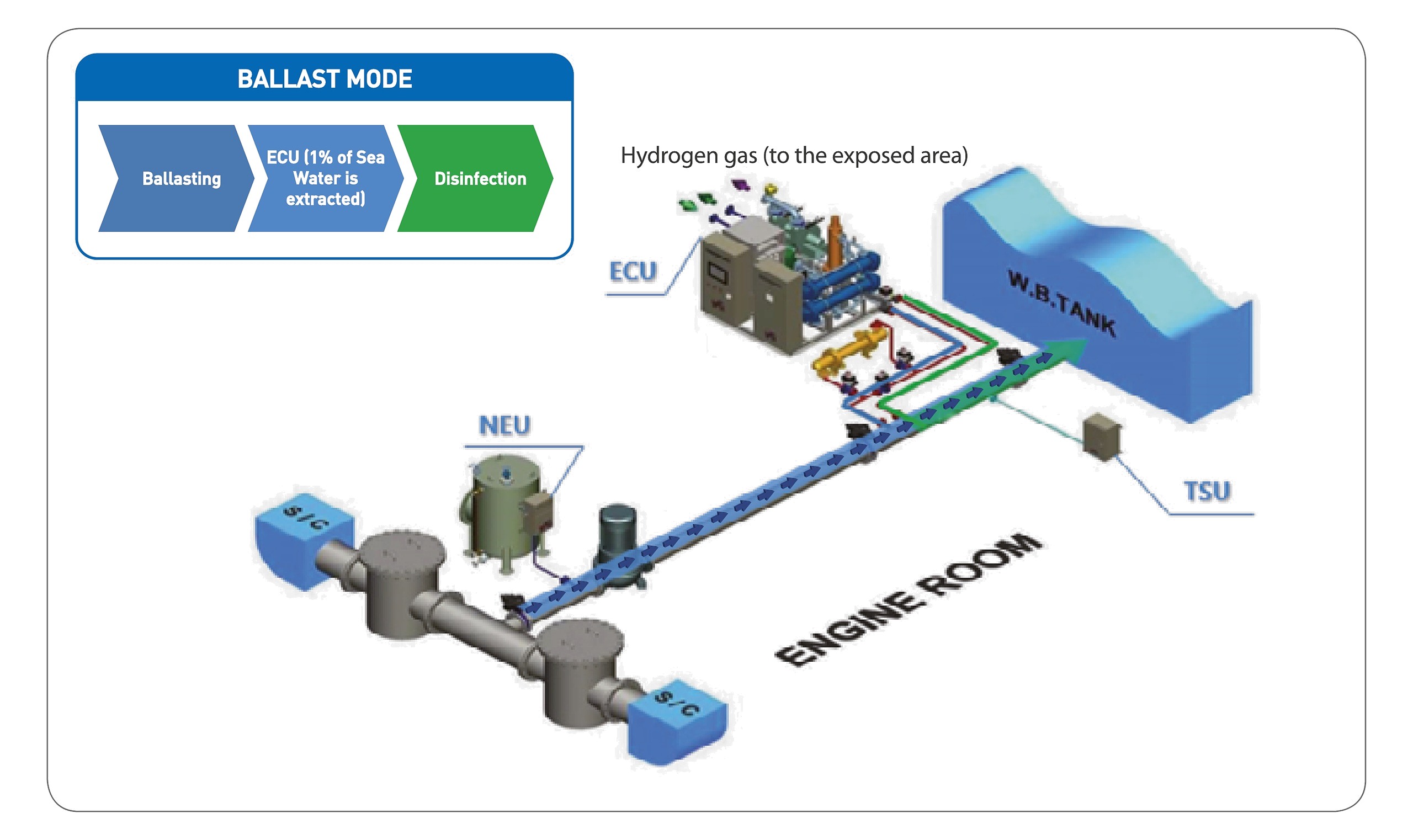
About one per cent of the ballast flow is drawn off into the electro chlorination unit. Electrolysing sea water there produces a concentrated dose of total residual oxidants, and that dose goes straight back into the main ballast line, where it disinfects the plankton, larvae, spores and pathogens on their way to the tank. Hydrogen from the reaction is separated by a degassing system and vented to an exposed area.
Because only the side stream passes through the equipment, the units do not have to sit in the ballast main. They go wherever there is room, and the main line needs very little cutting about — on a retrofit that is usually the difference between a straightforward job and a difficult one. There is no filter to foul, so the system works in turbid water, and nothing is carried in stock: the oxidant is made from sea water as it is needed.
De-ballasting — neutralisation
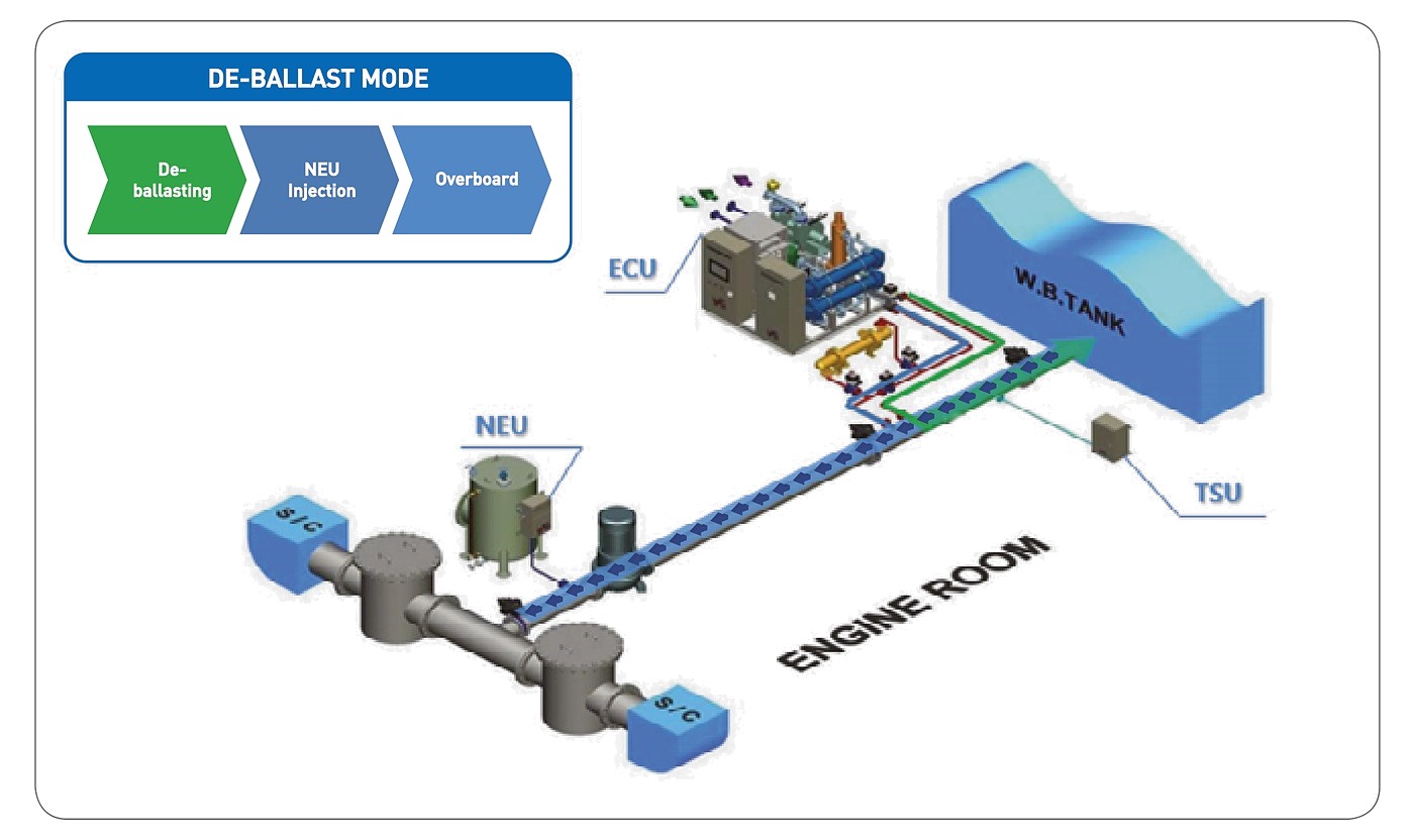
On discharge the process runs the other way. The neutralisation unit meters sodium thiosulphate into the treated water and the TRO sensor watches the reading as it goes, so the water only passes overboard once the oxidant is down. The dosing is metered against the reading rather than run open loop, which keeps the thiosulphate consumption to what the water actually needs.
The units
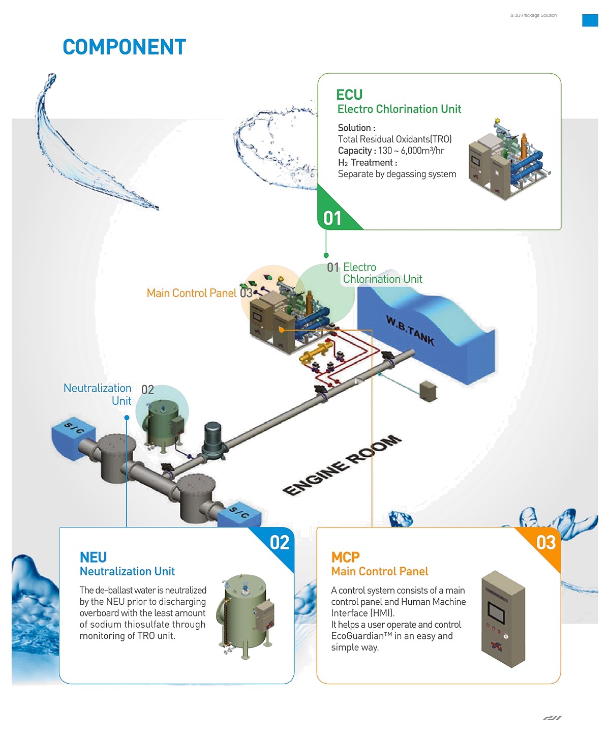
| ECU — electro chlorination unit | Makes the total residual oxidants from the side stream. 130 to 6,000 m³/h. Electrolytic cells, rectifier and transformer, booster pump, conductivity sensor and degassing device. Hydrogen separated by the degassing system |
|---|---|
| NEU — neutralisation unit | Doses sodium thiosulphate on de-ballasting, under TRO monitoring |
| SIU — sampling and injection unit | Takes the side stream off the main and returns the treated stream to it |
| HEU — hydrogen exhaust unit | Carries the hydrogen from the degassing system to an exposed area |
| MCP — main control panel | PLC and human machine interface with a touch screen. Automatic operation, with manual operation by remote control as an option |
General specification
| Treatment method | Side-stream electrolysis on ballasting; neutralisation on de-ballasting |
|---|---|
| Biological efficiency | IMO D2 performance standard and 33 CFR 151.2030 (BWDS) |
| Capacity | 130 to 6,000 m³/h |
| Operation | Automatic, or manual by remote control as an option |
| Operator interface | Human machine interface, touch screen |
| Services required | Control air at 6 to 7 kgf/cm² for the pneumatic valves; fresh water for rectifier cooling |
| Installation | Skid mounted, containerised, or as separate units |
| Hazardous area | Every model is offered in a standard and an Ex version |
Range and dimensions
Fourteen sizes, each in a standard and an Ex version. The figures below are the footprint in square metres and the weight in tonnes of the electro chlorination unit, which is the largest of the units. Footprints for the neutralisation, sampling and hydrogen exhaust units run from about 0.1 to 2.4 m³. Take these as indicative and confirm against the certified drawing for the model selected.
| Model | Capacity | ECU footprint / weight | Model | Capacity | ECU footprint / weight | |
|---|---|---|---|---|---|---|
| EGNF0130 | 130 m³/h | 2.6 m² / 1.2 t | EGNF2000 | 2,000 m³/h | 10.6 m² / 3.9 t | |
| EGNF0250 | 250 m³/h | 2.6 m² / 1.4 t | EGNF2600 | 2,600 m³/h | 10.2 m² / 4.6 t | |
| EGNF0350 | 350 m³/h | 2.9 m² / 1.5 t | EGNF3000 | 3,000 m³/h | 10.6 m² / 5.5 t | |
| EGNF0500 | 500 m³/h | 3.2 m² / 1.7 t | EGNF3600 | 3,600 m³/h | 14.3 m² / 5.9 t | |
| EGNF0800 | 800 m³/h | 5.0 m² / 2.2 t | EGNF4000 | 4,000 m³/h | 18.9 m² / 9.4 t | |
| EGNF1000 | 1,000 m³/h | 5.4 m² / 2.3 t | EGNF5200 | 5,200 m³/h | 10.0 m² / 8.1 t | |
| EGNF1500 | 1,500 m³/h | 7.9 m² / 3.3 t | EGNF6000 | 6,000 m³/h | 16.5 m² / 9.3 t |
Retrofit

| Survey | Pre-survey against the piping diagram, port status, P&ID and scope of supply, then a main survey on board with 3D scanning, and a proposal with costs |
|---|---|
| Design and manufacture | Drawings for owner and for class, material purchase, manufacture, inspection and delivery |
| Installation | Preparation of the installation place, loading on board, installation, pipe work, cable work and sea trial |
| Why side-stream helps | Only the side stream passes through the equipment, so the main line needs minimum modification and the units can be sited where there is room rather than where the ballast line runs |
The 3B ballast package
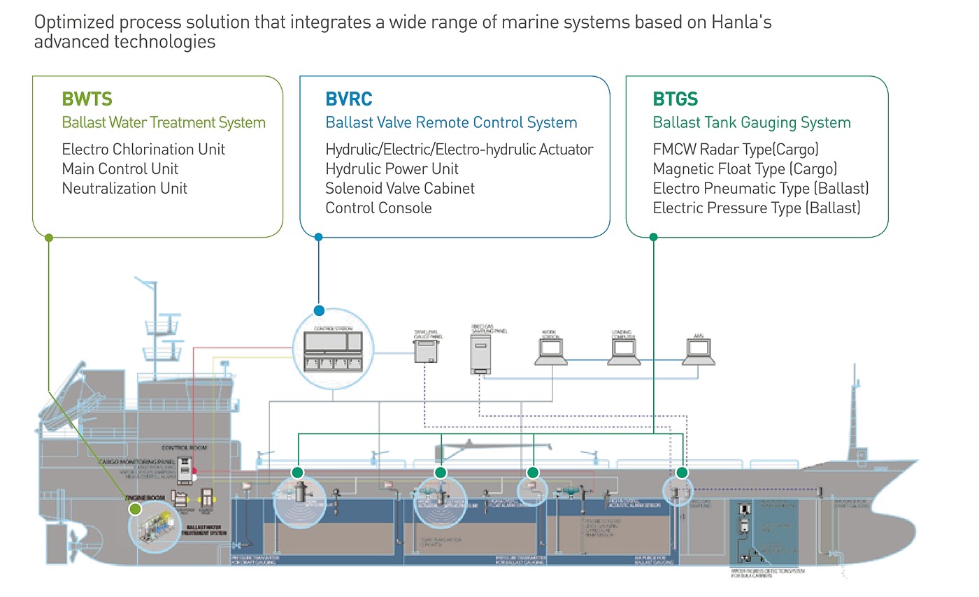
Hanla supplies the treatment system, the ballast valve remote control system and the ballast tank gauging system as one package, tied together through the Dynamic-A integrated ballast control console. The console shows the treatment system’s operating status, works the ballast valves in step with it, and reads the tank levels back — so the level signal can stop the treatment system when a tank is full.
| BWTS | Electro chlorination unit, main control unit, neutralisation unit |
|---|---|
| BVRC | Hydraulic, electric, electro-hydraulic actuators; hydraulic power unit; solenoid valve cabinet; control console |
| BTGS | FMCW radar and magnetic float for cargo; electro pneumatic and electric pressure for ballast |
| Why one supplier | One commissioning rather than four, one delivery, and one party responsible for the integration |
Approvals
- IMO type approval of the ballast water treatment system, and IMO final approval of EcoGuardian
- USCG type approval, 2019; USCG AMS approval, 2016
- Compliance with the IMO D2 performance standard and 33 CFR 151.2030
- Class type approvals from ABS, KR, LR, DNV, BV and NK
- Ex versions of every model for hazardous area installation
Send the ballast pump capacity, the ballast line arrangement and the space you have, and we will size the system and quote. For a retrofit, the general arrangement and the engine room piping diagram are enough to start.