
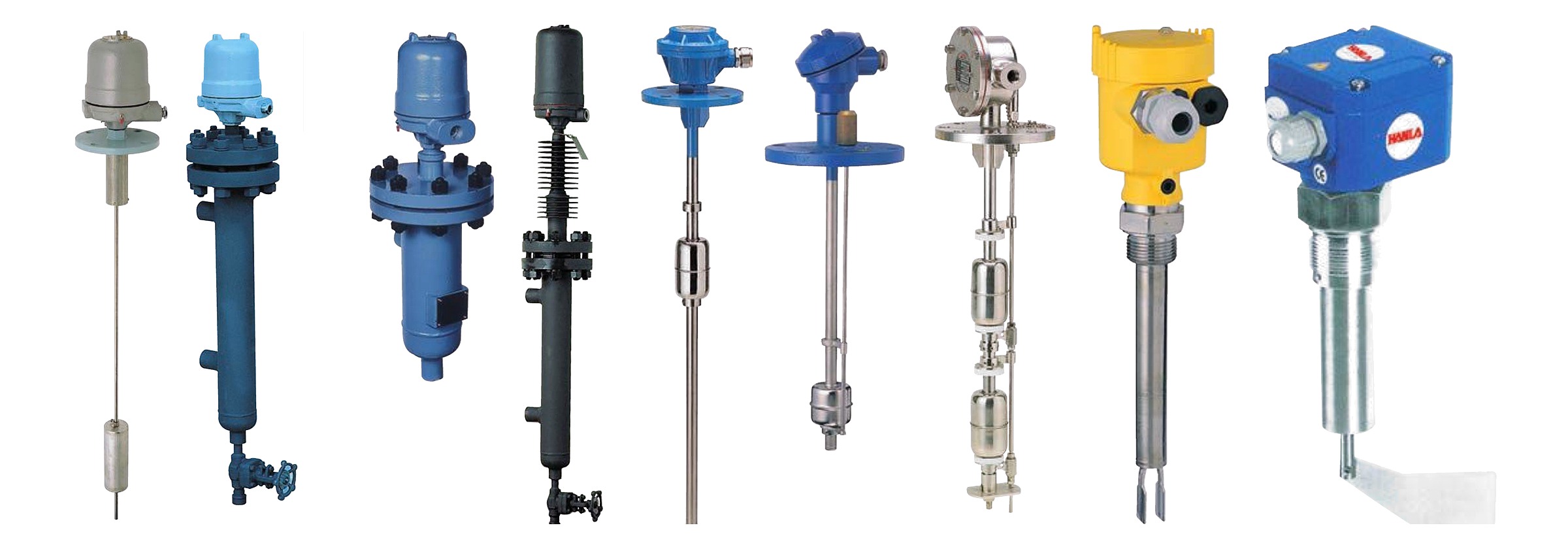
Point level detection for shipboard tanks and silos — magnetic float, displacement, reed, pneumatic diaphragm, capacitive, vibrating fork and rotating paddle. Weatherproof IP56 or explosion proof Exd IIC T6, contacts rated to 250 V AC 15 A, and models for clean liquids, sludge and dry bulk.
On this page
- Micro switch type float switch›
- Displacement type level switch›
- Float operated type level switch›
- Reed switch type float level switch›
- Pneumatic type level switch›
- Quick float type level switch›
- Capacitive type oil detector›
- Vibration type level switch›
- Paddle type level switch for solids›
- Flow detection switch›
Micro switch type float switch
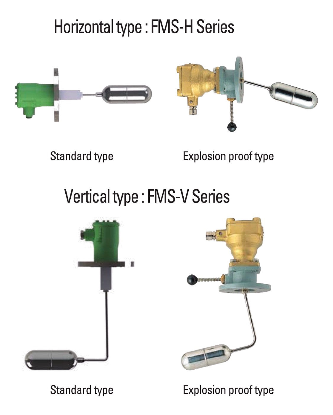
Model: FMS series. A magnet in the float arm and a second magnet on the switch unit act on each other through a non-magnetic diaphragm, so the switch unit is completely separated from everything inside the tank. That separation is what makes the switch fully sealed: nothing electrical is exposed to the liquid.
The floats are argon-gas welded stainless steel, durable against both pressure and temperature. The switch unit is simply built for easy maintenance and carries a large 250 V AC 5 A contact. Horizontal (FMS-H) and vertical (FMS-V) versions are available, each in standard and explosion proof form.
Used on heavy fuel oil, settling, sludge, sewage, fresh water, lubricating oil and diesel oil tanks.
| Type | Application | Max. pressure | Max. temp. | Contact rating | Min. Sp.Gr | Cable entry | Float | Flange | Switch body |
|---|---|---|---|---|---|---|---|---|---|
| Standard | General liquid | 10 kg/cm² | 180 °C | 250 V AC, 5 A | 0.78 | 15b (PF 1/2″) | SUS 304 | ADC | ADC |
| Differential | Widely differential | 10 kg/cm² | 180 °C | 250 V AC, 5 A | 0.80 | 15b (PF 1/2″) | SUS 304 | ADC | ADC |
| Explosion proof | Hazardous area | 10 kg/cm² | 180 °C | 250 V AC, 5 A | 0.78 | NPT 1/2″ | SUS 304 | SUS 304 | SCS 13 |
Contact forms: SPDT, DPDT, or SPDT special type with reed switch. C–A makes on rising level, C–B makes on falling level. Connection sizes: 1 A-flange (square), 2 JIS 5K 65A (standard), 3 other size. Options: SUS 304 or SUS 316 wetted parts including float and flange; 3/4″ cable entry to JIS F 20 a, b or c; larger flanges. Non-explosion-proof models can be used as intrinsically safe when joined with an I.S. barrier.
Displacement type level switch
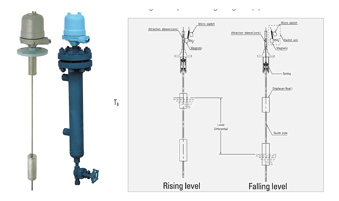
Model: DMS series. A weighted displacer hangs from a compression spring. As the liquid rises the displacer becomes buoyant, the spring retracts, and an attraction sleeve moves up into the field of a magnet in the switch unit, changing the micro switch contact. Because the switching point is set by where the displacer sits on the guide pipe, it can be moved after installation.
The displacer is heavier than the liquid and is barely affected by agitation, which is what makes this type suit tanks that are being stirred or pumped. Contacts are rated 250 V AC 15 A, and the unit is fully sealed.
Used on coal tar fuel, heavy fuel oil, settling, sludge, sewage, fresh water, lubricating oil and diesel oil tanks, and bilge wells.
| Model | Main application | Max. setting range | Setting accuracy | Min. Sp.Gr | Max. press. | Max. temp. | Contact rating |
|---|---|---|---|---|---|---|---|
| DMS-01A | High or low alarm | 220 – 5,000 mm | ±8 mm | 0.85 | 10 kg/cm² | 180 °C | 250 V AC, 15 A |
| DMS-01C | High or low control | 220 – 5,000 mm | ±8 mm | 0.85 | 10 kg/cm² | 180 °C | 250 V AC, 15 A |
| DMS-02A | High and low alarm | 220 – 4,500 mm | ±8 mm | 0.85 | 10 kg/cm² | 180 °C | 250 V AC, 15 A |
| DMS-02C | High and low control | 220 – 4,500 mm | ±8 mm | 0.85 | 10 kg/cm² | 180 °C | 250 V AC, 15 A |
| DMS-03AC | High alarm / mid. and low control | 220 – 4,000 mm | ±8 mm | 0.85 | 10 kg/cm² | 180 °C | 250 V AC, 15 A |
| DMS-03CA | High and mid. control / low alarm | 220 – 4,000 mm | ±8 mm | 0.85 | 10 kg/cm² | 180 °C | 250 V AC, 15 A |
All models are top flange type with 15b cable entry, ADC housing, SS41 flange, and SUS 304 float and float chamber.
| Switch units | Model | Upper differential | Lower differential |
|---|---|---|---|
| One | DMS-01A / 01C | 30 to 50 mm | – |
| Two | DMS-02A / 02C | 30 to 50 mm | 30 to 50 mm |
| Two | DMS-03AC | 30 to 50 mm | 200 to 4,500 mm |
| Two | DMS-03CA | 200 to 4,500 mm | 30 to 50 mm |
Internal construction options: G without float chamber, C with float chamber, R guide wire, SS with external float chamber for side–side mounting. Enclosure: W weatherproof IP56, E explosion proof IP56 / Exd IIC T6. SUS 316 wetted parts, 3/4″ cable entry and I.S. barrier operation are available on request.
Float operated type level switch
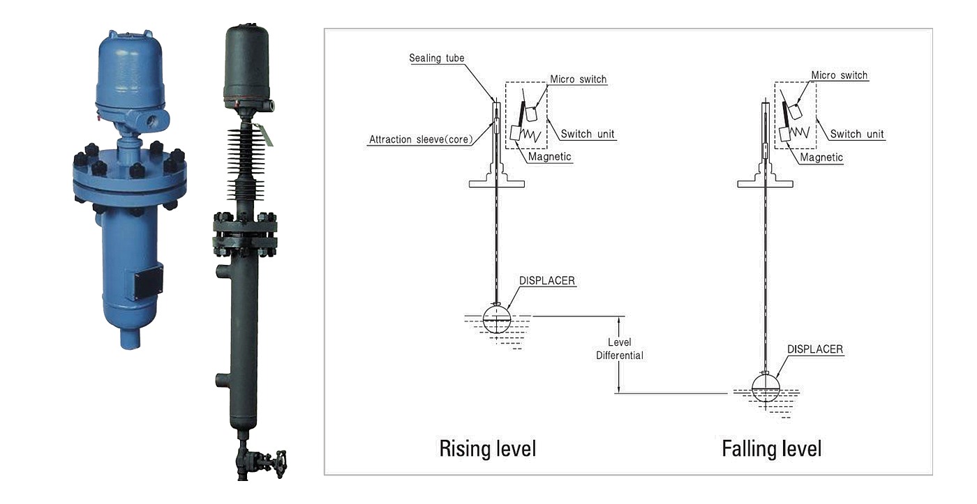
Model: OMS series. The displacer and the switch unit sit in an external chamber alongside the tank. Buoyancy moves an attraction sleeve, and a magnet changes the micro switch contact. The switching point can be trimmed by up to 15 mm by moving the switch unit itself, without touching the displacer.
Dry contact mechanisms are recommended where the environment is critical, and are supplied in both SPDT and DPDT; a maximum of two mechanisms per control is standard. The mechanisms are built in rugged stainless steel and the switch has high load carrying capacity and good vibration resistance.
| Model | Chamber material and pipe size | Max. switch mechanisms | 100 °F | 750 °F | 38 °C | 400 °C max. | Min. Sp.Gr |
|---|---|---|---|---|---|---|---|
| OMS-F401 | Carbon steel (4″) | 2 | 285 psig | 95 psig | 20 bar | 7 bar | 0.57 |
| OMS-F402 | Carbon steel (4″) | 2 | 600 psig | 450 psig | 41 bar | 31 bar | 0.65 |
| OMS-F301 | Carbon steel (3″) | 1 | 285 psig | 95 psig | 20 bar | 7 bar | 0.67 |
| OMS-F302 | Carbon steel (3″) | 1 | 350 psig | 260 psig | 24 bar | 18 bar | 0.67 |
| OMS-S401 | Carbon steel (4″) | 2 | 600 psig | 450 psig | 41 bar | 31 bar | 0.65 |
| OMS-S301 | Carbon steel (3″) | 1 | 300 psig | 225 psig | 21 bar | 16 bar | 0.57 |
| OMS-S302 | Carbon steel (3″) | 1 | 350 psig | 260 psig | 24 bar | 18 bar | 0.67 |
| OMS-SF | Carbon steel | 1 | 230 psig | 95 psig | 16 bar | 7 bar | 0.50 |
| OMS-TF | Carbon steel | 1 | 225 psig | 165 psig | 16 bar | 11 bar | 0.81 |
| OMS-S303 | Carbon steel | 1 | 285 psig | 95 psig | 20 bar | 7 bar | 0.70 |
Control pressure rating is given at 100 °F and 750 °F in psig, and at 38 °C and 400 °C maximum in bar. Every model carries an SPDT contact rated 120 V AC 15 A.
| Radiation fin | Wings | Temperature range |
|---|---|---|
| Not provided | – | 0 to 110 °C |
| F4 | 4 | 110 to 200 °C |
| F6 | 6 | 200 to 250 °C |
| F9 | 9 | 250 to 310 °C |
Nominal dimensions depend on the minimum differential setting, the minimum liquid specific gravity and single switch function; the published dimensions are for 1″ NPT or socket weld type only. Connection method: SS side–side, SB side–bottom, SV side–bottom–side. Connection sizes: S1 1″ socket weld, S1½ 1-1/2″ socket weld, S2 2″ socket weld, F1 JIS 5K 25A, F2 JIS 16K 25A, FS special flange (ANSI, DIN).
Reed switch type float level switch
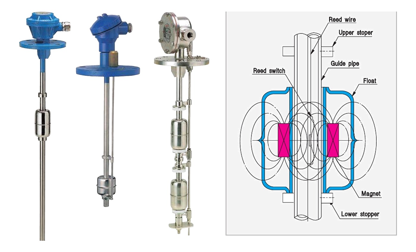
Model: TMR series. A magnet is built into the float and a set of reed switches sits inside the guide pipe. As the float rides up and down with the level, the switches make and break. Stoppers above and below limit how far the float can travel, so the reed contact self-holds rather than chattering around the set point.
Up to six detection points can be carried on one stem, and up to three of them can be terminated independently as desired. The arrangement is the same whether the unit carries one detection point or six, so a single stem can cover high and low alarm together with pump auto start and stop.
Compact, totally enclosed electrics, in stainless steel and plastic models, for water, seawater, oil and general liquids.
| Model | Application | Max. press. | Max. temp. | Mounting flange | Min. Sp.Gr | Max. detection points | Float / guide pipe |
|---|---|---|---|---|---|---|---|
| TMR-5∗5S-G | General liquid (oil, water) | 10 kg/cm² | 80 °C | JIS 5K 80A | 0.85 | 6 | SUS 304 / SUS 304 |
| TMR-5∗5S3-G | Anti-corrosive liquid | 10 kg/cm² | 80 °C | JIS 5K 80A | 0.85 | 6 | SUS 316 / SUS 316 |
| TMR-4∗5R-G | Low specific gravity liquid | 5 kg/cm² | 70 °C | JIS 5K 65A | 0.60 | 6 | Resin / SUS 304 |
| TMR-8∗5P-G | Anti-corrosive liquid | 3 kg/cm² | 50 °C | JIS 10K 100A | 0.70 | 6 | P.V.C / P.V.C |
| TMR-P1∗5RS-G | Mini vessel | 5 kg/cm² | 70 °C | PF 1/4 | 0.70 | 2 | Resin / SUS 304 |
| TMR-P1∗5SS-G | Mini vessel | 10 kg/cm² | 80 °C | PF 1/4 | 0.90 | 2 | SUS 304 / SUS 304 |
| TMR-4∗6S-G | General liquid | 10 kg/cm² | 80 °C | JIS 5K 65A | 0.85 | 6 | SUS 304 / SUS 304 |
Top flange connection on the flanged models and thread type on the PF 1/4 models; cable entry 15b; contact form and rating SPST 250 V AC 0.5 A on every model. ∗ marks the switch-function code in the model number — 1A high or low alarm, 2A high and low alarm, 2C high and low control, 3CA high and mid. control / low alarm, 3AC high alarm / mid. and low control, 4AC high-high and low-low alarm with high and low control. Float sizes: 5S Ø65×111L SUS 304, 5S3 Ø65×111L SUS 316, 5R Ø50×45L resin, 6S Ø50×47.5L SUS 304, 5P Ø76×100L P.V.C, 5RS Ø26.5×25L resin, 5SS Ø28×25L SUS 304. Enclosure: W weatherproof IP56, E explosion proof IP67 / Exd IIC T6, SB submergible IP68. Ratings are given for the empty tank condition.
Pneumatic type level switch
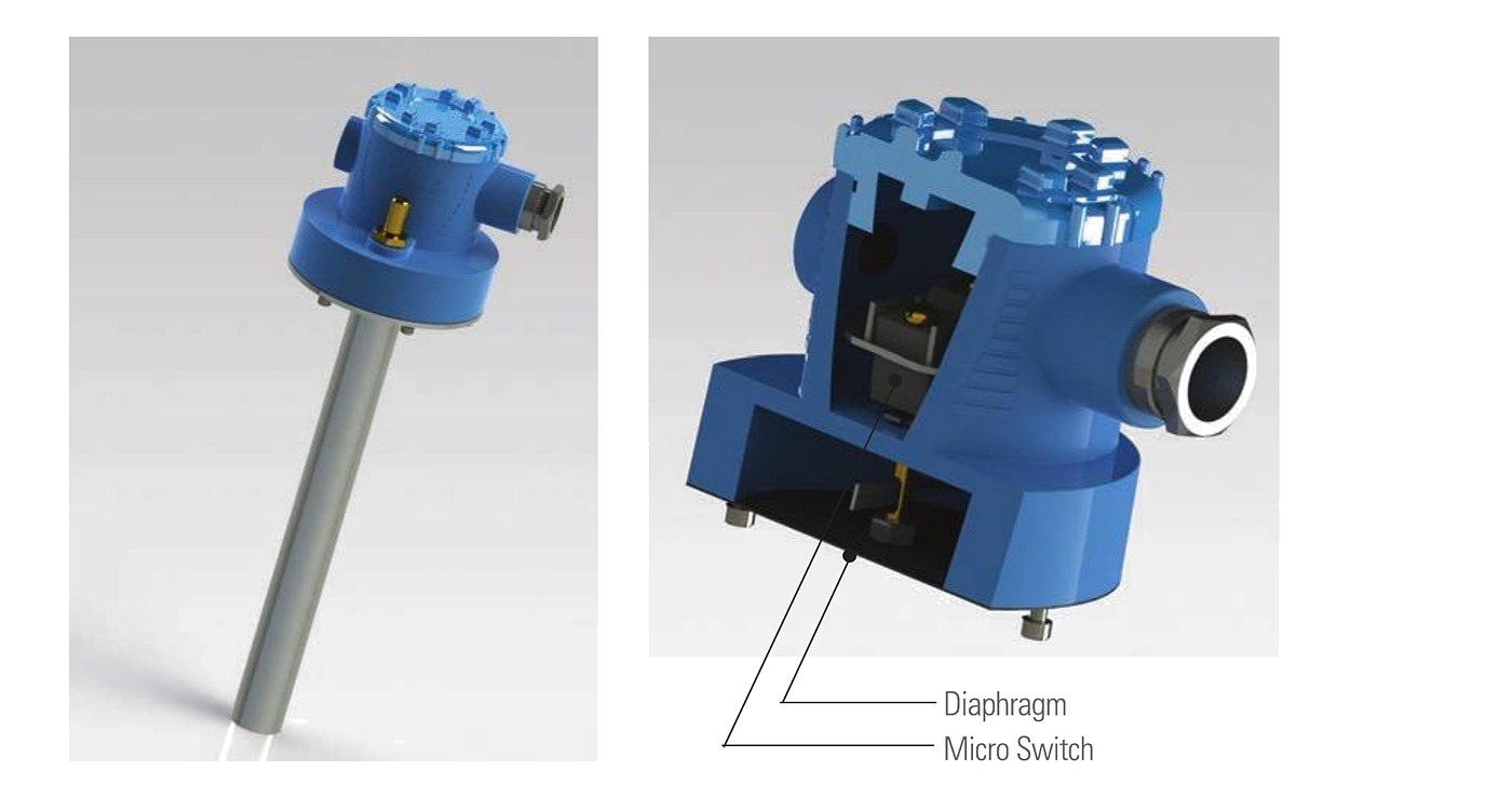
Model: HPS. A diaphragm alarm switch with nothing inside the tank. Liquid pressure is transferred up a pipe and moves a pleated diaphragm against the air pressure behind it, which operates a micro switch. Because there is no float unit and no contact with the liquid, this is the type to reach for on sludge and high-viscosity media where a float would foul or a displacer would coat.
The pleated diaphragm gives high reliability and stable behaviour, and the design is free of the corrosion and adhesion troubles that affect wetted mechanisms. A lifting-type manual test device lets the function be checked in service.
Used on heavy oil, lubricant, centrifugal separator and stirring tanks, bilge and sewage, water making equipment, water treatment, asphalt plant, and foodstuff and beverage machinery.
| Contact form and rating | SPDT, 250 V AC 15 A |
|---|---|
| Accuracy | ±5 mm on level rise or fall |
| Max. working pressure | 1 kg/cm² |
| Max. working temperature | 80 °C |
| Working point | 65 mm |
| Reset point | 45 mm |
| Differential | 20 mm |
| Min. pipe length | 100 mm |
| Enclosure | IP66 / 68 |
| Materials | Cover and main body aluminium die-casting; lower body and pipe SUS 304; diaphragm NBR |
| Connection size | JIS 5K 65A standard, other sizes to order |
Quick float type level switch
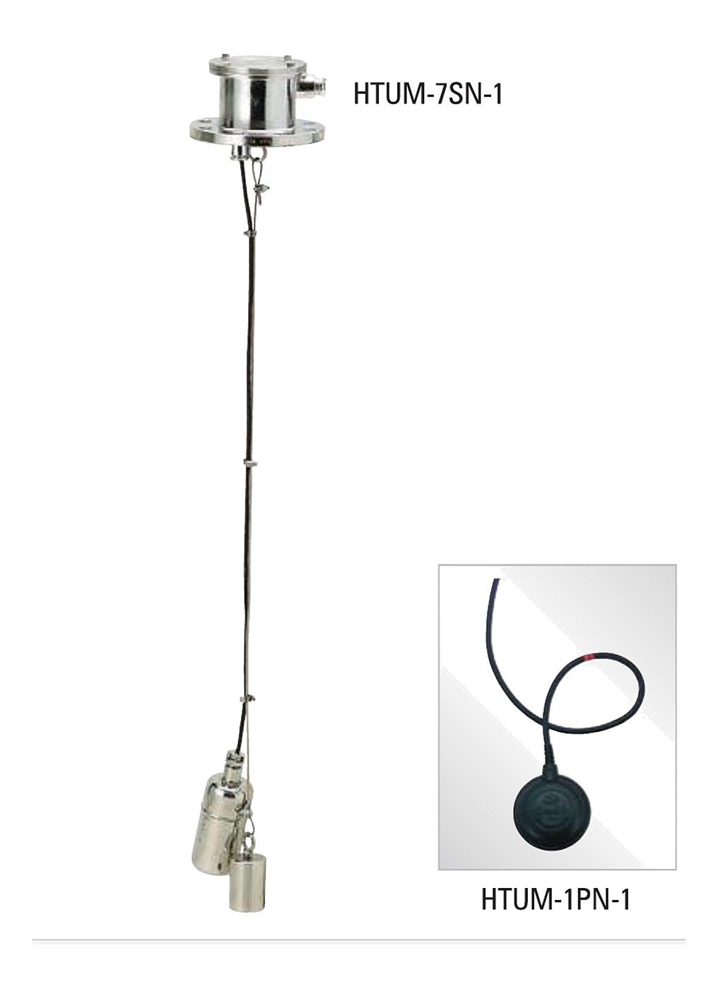
Model: HTUM series. A reed or micro switch unit sits inside a float casing on the end of a cable, sealed so the casing and cable are one assembly. As the float tips with the liquid level, the contact opens or closes. Simple, low cost, and easy to install and maintain.
This is an atmospheric-pressure, ambient-temperature product — wells, locks and rivers, and waste water, sewage, drain and sludge tanks.
| Model | Connection | Float material | Max. press. | Max. temp. | Switch type | Contact form and rating | Max. cable length |
|---|---|---|---|---|---|---|---|
| HTUM-7PN | Top flange | Polypropylene | 10 kg/cm² | 60 °C | Micro switch | SPDT, 250 V AC 10 A | 10,000 mm |
| HTUM-7SN | Top flange | Stainless steel (SUS 304) | 10 kg/cm² | 80 °C | Reed switch | SPST or SPDT, 250 V AC 0.5 A | 5,000 mm |
Float protection is IP68 and the switching distance 10 to 50 mm on both, with 20 (PF 3/4) cable entry. Model code: HTUM – connection size (1 without housing, 7 JIS 5K 100A, 8 JIS 10K 100A) – float material (PN polypropylene, SN stainless steel SUS 304) – number of floats, 1 to 4.
Capacitive type oil detector
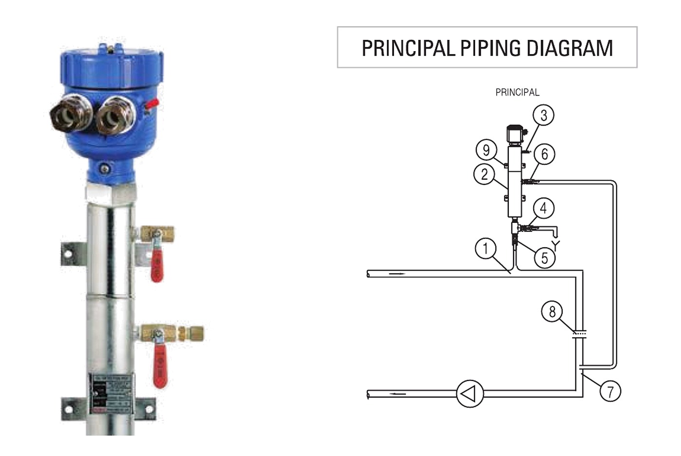
Two arrangements of the same capacitive sensing element, one for a pipeline and one for a tank.
On the piping line. Installed in the cooling water line of the ship to detect oil in the cooling water. The system is an oil detection pot, a capacitive compact switch and a control unit. The pot separates oil from water; the switch sits in the oil above the water and is isolated from it, and the control unit converts the signal to a relay contact.
| Max. pressure | 5 kg/cm² |
|---|---|
| Max. temperature | 110 °C |
| Flow | 100 – 300 litre/h |
| Sensitivity | Approx. 50 ml of oil |
| Power supply | AC 110 / 220 V |
| Output | Relay output, DPDT |
On the tank. A boiler feed filter tank has an inspection chamber where oil accumulates. Under normal conditions the end of the electrode sits in water. When oil-contaminated water enters, the feed water passes on to the filter tank while the oil collects in the inspection chamber until it is drained; once the oil layer reaches the electrode, the detector alarms. After the chamber is drained the detector returns to normal.
| Type | Capacitive oil detector |
|---|---|
| Power supply | AC 110 / 220 V |
| Output | Relay contact, DPDT |
| Operating pressure | 10 bar |
| Max. temperature | 100 °C |
| Protection | IP66 |
| Connection size | G 1-1/2″ |
Vibration type level switch
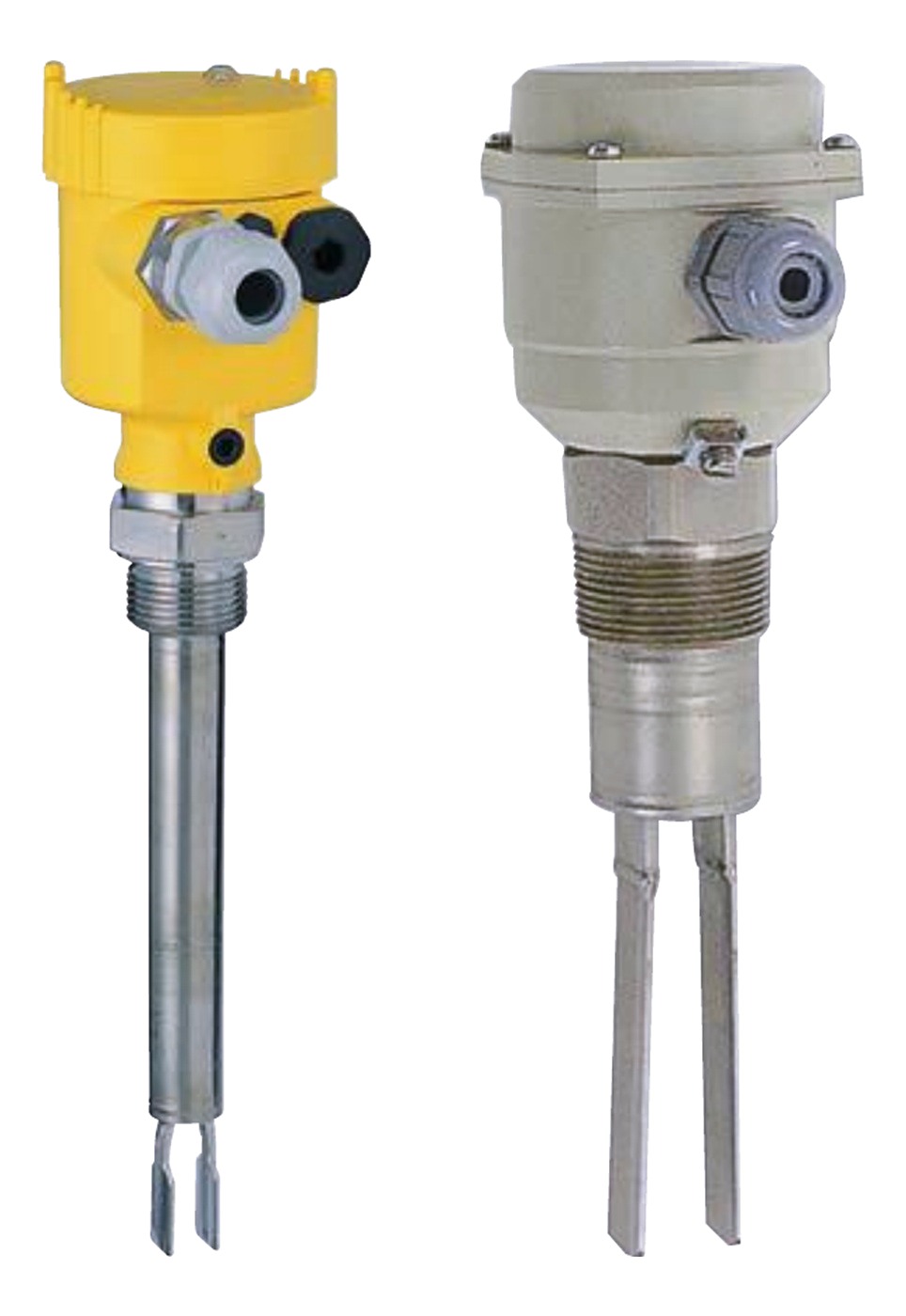
A tuning fork is driven piezo-electrically at its mechanical resonance of 125 Hz. When the product covers the fork the vibration is damped, the damping is registered electronically and the output switches. The oscillation also keeps the fork clean, which is what makes the type suitable in products that tend to build up.
SWING series is the liquid switch, with universal power input, self-diagnostic electronics and a choice of four outputs.
| Power source | 20 – 250 V AC, 20 – 250 V DC |
|---|---|
| Power consumption | Max. 3 N |
| Output | Relay output 1 × SPDT, transistor output, or non-contact switch |
| Viscosity range | 0.2 – 10,000 mPas |
| Density range | 0.7 – 2.5 g/cm³ |
| Protection | IP66 |
HVPS series covers liquids and bulk solids, and is used in all types of container and silo with powdery and granulated materials that do not form crusts or deposits.
| Materials | Housing ADC; connector SUS 304; tuning fork SUS 304 |
|---|---|
| Max. pressure | 16 bar |
| Max. temperature | 200 °C |
| Enclosure | IP65 |
| Main voltage | AC 230 V / AC 115 V / DC 24 V |
| Installed load | Max. 1 A (relay) |
| Output | 1 × SPDT |
| Min. powder density | Approx. 30 g/L |
| Cable gland | PG 13.5 |
HVPS shape of vibration: 2020 standard design, 2030 extension probe to 4 m, 2050 extension cable to 20 m. Product temperature codes: NT to 100 °C, HT to 150 °C, AT to 200 °C with air cooling device. Enclosure: W weatherproof IP56, E explosion proof IP56 / Exd IIC T6.
Paddle type level switch for solids
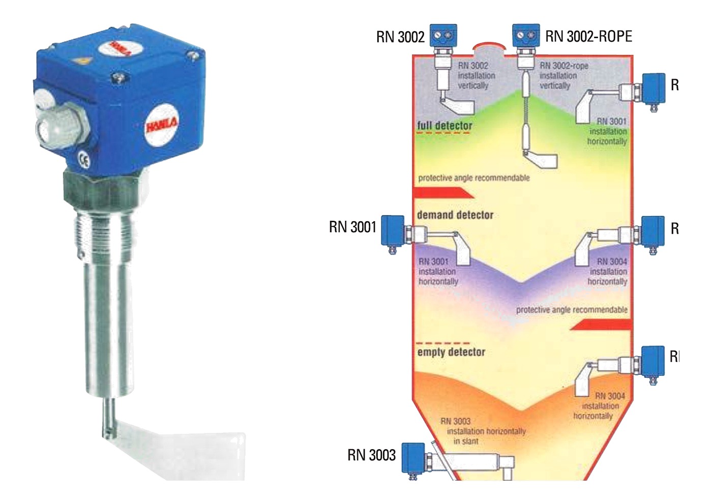
Model: RN 3000 series. A low-revolution synchronous induction motor turns a measuring vane inside the container. When the material reaches the vane it is stopped in its rotation. The motor is freely suspended in the housing, so the reaction torque swings the motor body, operates a micro switch and cuts the drive. When the level drops and the vane is free again, a spring draws the motor back to its working position and the switch resets.
Used wherever the product is dustlike, powdery, granulated or granular. Appropriate for powder and granulated bulk goods, reliable, maintenance-free and small.
| Materials | Die-cast housing; steel-galvanised or stainless connector; SUS 304 vane shaft |
|---|---|
| Process connection | Thread or flange, according to selection |
| Enclosure | IP65 |
| Vane speed | 11 rev/min |
| Pick-up delay | Approx. 1.3 s |
| Mains voltage | 220 – 240 V or 110 – 200 V, 50 – 60 Hz |
| Signal output | 1 × SPDT micro switch |
| Cable gland | 1 × PG 13.5 |
| Pressure | Max. 0.8 bar / 5 bar / 10 bar |
| Temperature | Max. 80 °C / 150 °C / 220 °C |
| Powder density | Down to 20 g/L |
Six models, RN 3001 to RN 3006 plus RN 3002-ROPE, cover full, demand and empty detection and vertical, horizontal or oblique mounting. Not every model is suitable for dust Ex zone 10/11 — check the selection guide before ordering.
Flow detection switch
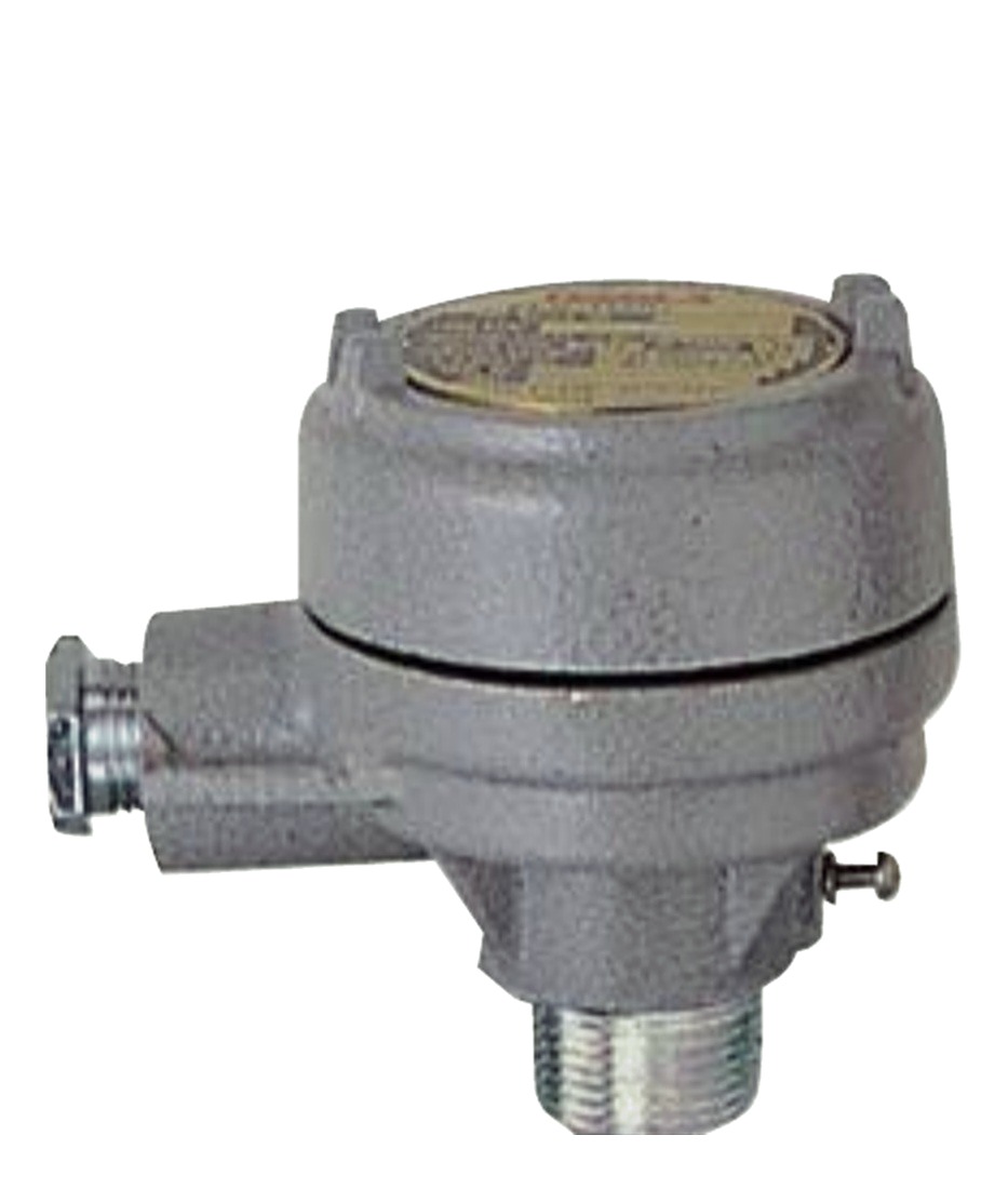
Model: FWS-3P. Not a level switch, but built on the same micro-switch head and often ordered alongside one. It protects equipment or a pipeline when flow falls or rises beyond the set point. Hydrostatic pressure from the flowing liquid moves a paddle and lever, which operates the micro switch in the housing; when flow stops, the spring returns the lever to its normal position.
Used to protect pumps and motors, to control pumps, and to start pumps and engines.
| Mounting | Screw or flange, 1″ PT |
|---|---|
| Working pressure | Atmospheric, max. 0.2 kg/cm² |
| Process temperature | 60 °C standard, 120 °C option |
| Enclosure | Weatherproof IP56 |
| Materials | Head AC; connector BS; paddle SUS 304 |
| Conduit connection | 3/4″ PF(F) |
| Switch type and output | Micro switch, 1 × SPDT |
| Contact rating | 250 V AC, 15 A |
For continuous level rather than point alarms, see level transmitters. For direct reading at the tank, see level gauges. Where the alarms have to be gathered on a console, see tank monitoring systems.